
1. Product Introduction
Built-in overcurrent, overvoltage, short-circuit protection, and soft-shutdown functions ensure safe operation of power devices. For example, the HL403B driver extends the output pulse current through a push-pull circuit, with a peak value of ±6A, making it suitable for driving high-power IGBT modules. It provides high-current pulses (typically 1-18A) to quickly charge and discharge the gate capacitance of power devices and reduce switching losses.
2. Technical Features
- Core Functions: This module integrates gate drive and parallel feedback functions, supporting drive control of power devices such as IGBTs/MOSFETs. It achieves precise switching status monitoring and protection through isolated current/voltage feedback. For example, similar models in GE’s Mark V/VI series (such as the DS200IIBDG1A) use opto-isolated gate drive circuits, with each output phase equipped with an independent drive channel, supporting real-time feedback of current, voltage, and fault signals.
- Protection Mechanisms: Built-in overcurrent, overvoltage, short-circuit protection and soft-shutdown functions ensure safe operation of power devices. For example, the HL403B driver expands the output pulse current through a push-pull circuit, with a peak value of ±6A, suitable for driving high-power IGBT modules.
- Drive Capability: Provides high-current pulses (typically 1-18A) for rapid charging and discharging of power device gate capacitance, reducing switching losses.
- Isolation and Protection: Employs optoelectronic/magnetic/capacitive isolation technology, featuring intelligent protection functions such as undervoltage protection, overcurrent/overvoltage protection, Miller clamping, and desaturation detection.
- Performance Parameters: Typical drive capabilities cover high-side/low-side configurations, supporting 3-phase drive architectures. Operating voltage range is typically 15-24V, with response times down to the nanosecond level (e.g., the DRV8300 series driver has a response time of approximately 12ns), suitable for high-frequency switching applications. Package types are mostly industrial-grade standards (e.g., QFN, DIP), adaptable to harsh environmental requirements.
- Feedback Mechanism: Integrated current/voltage feedback circuit for real-time monitoring of power device status, supporting fault diagnosis and dynamic adjustment.
- Electrical Characteristics: Typically operates at 15-18V, supports wide operating temperature (-40°C to 70°C), and has strong shock resistance (e.g., 30g/11ms).
3. Application Scenarios
Industrial Control: Widely used in gas turbines, wind power generation, rail transportation, and other scenarios. In GE’s Mark VI system (such as the IS200JPDAG1A current feedback board), this module is used for turbine control, achieving precise power regulation and fault diagnosis.
Power Electronics: Used as a core drive unit in converters, inverters, and other equipment to improve system efficiency and reliability. For example, a three-phase full-bridge inverter uses a parallel feedback module to achieve synchronous drive and status monitoring of multiple IGBT units.
Automation Systems: Adapts to DCS (Distributed Control System) and FCS (Fieldbus Control System), supports modular architecture and digital communication, meeting the high precision and high reliability requirements of Industry 4.0.
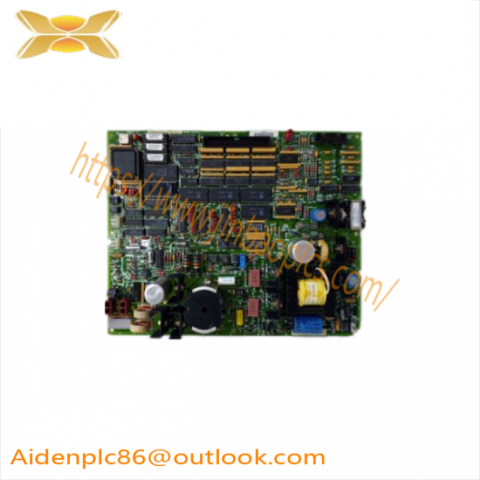
Summary: As a typical representative of GE industrial control modules, the IS200DSFCG1ADB holds an important position in the field of power electronics and automation due to its high-precision drive, multi-channel feedback, and strong environmental adaptability.
4. Comparison with Similar Models
Comparison with DS200IIBDG1A: Both belong to the GE Mark V system, but the IS200DSFCG1ADB may have optimized the parallel feedback module design, enhancing dynamic response and electromagnetic compatibility.
Comparison with Infineon’s Eice DRIVER series: GE products focus more on robust design for industrial scenarios, while Infineon’s solution has superior parameters for driving wide-bandgap devices (such as SiC/GaN).
5. Usage Precautions
Installation must follow anti-static guidelines; avoid touching other components in the cabinet.
When replacing components, connector identifiers must be matched to ensure cables are connected to the same ports.
Regularly check LED status indicators to monitor the board’s operating status.
There are no reviews yet.